VCTFK 300 V 60 °C PVC Multicore Cable
VCTFK 300 V flexible cord, 0.75–2 mm². O.D. 4.30 × 6.60 mm to 5.00 × 8.00 mm, stranded, 2 cores. Cut to length — quote on request.
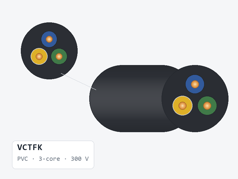
The source catalogue shows the PS E JET marking on selected JIS constructions, but no PSE certificate number has been supplied. Confirm the applicable category, marking and certificate for this exact style.
Request certificate or datasheet →VCTFK is a PVC-insulated flexible cord manufactured by Xinya Electronic Co., Ltd. It is rated 300 V. The catalogue describes it as a flat / oval section, heat-resistant construction. It is supplied in 2 recorded constructions spanning 0.75–2 mm², with an overall diameter of 4.30 × 6.60 mm to 5.00 × 8.00 mm, cut to the length you order.
VCTFK at a glance
- 0.75–2 mm², across 2 listed constructions
- Stranded conductor throughout the documented range
- Insulation wall 0.6 mm
- Overall diameter 4.30 × 6.60 mm to 5.00 × 8.00 mm
- Max. conductor resistance 9.5–24.4 Ω/km at 20 °C DC (roughly 2.9–7.4 Ω per 1,000 ft)
- Core counts listed: 2
How VCTFK compares with its nearest alternatives
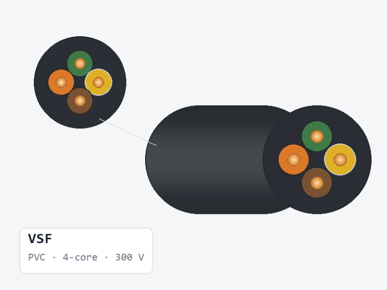
VCTFK and VSF share the 300 V rating and PVC insulation. Overall diameter is 4.30 × 6.60 mm to 5.00 × 8.00 mm against 2.5–3.4 mm for VSF. Insulation wall is 0.6 mm against 0.72 mm. Size coverage is 0.75–2 mm² against 0.5–2 mm².
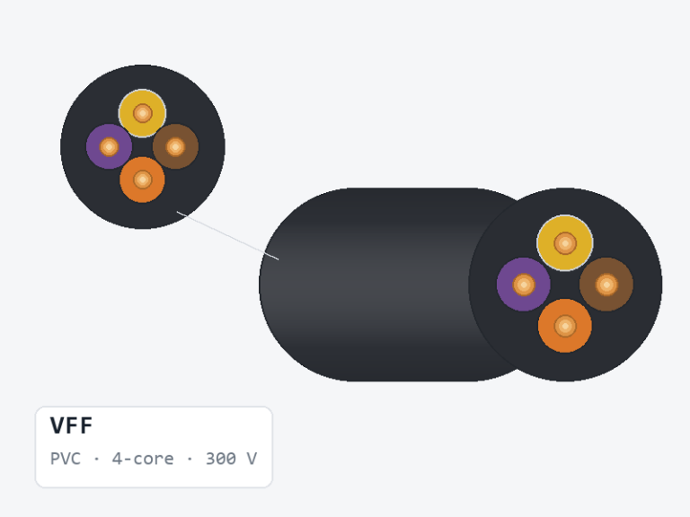
VCTFK and VFF share the 300 V rating and PVC insulation. Overall diameter is 4.30 × 6.60 mm to 5.00 × 8.00 mm against 2.50 × 5.60 mm to 3.40 × 6.80 mm for VFF. Insulation wall is 0.6 mm against 0.8 mm. Size coverage is 0.75–2 mm² against 0.5–2 mm².
Conductor construction and selection
Every construction listed for VCTFK is a stranded conductor, which suits harnesses and assemblies that are flexed or routed around a bend. The resistance column gives the maximum permitted value for the conductor at 20 °C DC.
How to read the VCTFK table
“Insulation O.D. (mm)” is measured over the insulation, not over a jacket, tape or braid. “Jacket O.D. (mm)” is the finished cable diameter, which is the value to quote for gland, grommet and connector sizing. Conductor resistance is stated at 20 °C DC per kilometre — divide by 3.281 for ohms per 1,000 ft.
Questions buyers ask about VCTFK
Which sizes of VCTFK are available?
0.75–2 mm², across the 2 constructions in the table below. Sizes outside the table can be quoted on request.
Is VCTFK a stranded conductor?
Every construction documented for this line is stranded. Confirm the strand count you need — the “n/mm” figure in the table — because resistance and flexibility both depend on it, and two rows at the same size can differ.
What overall diameter does VCTFK run to?
The documented range is 4.30 × 6.60 mm to 5.00 × 8.00 mm. Quote the size, not the style alone, when the diameter has to fit a specific gland, grommet or channel.
Manufacturer product data
- Rated temperature: VCTFK 60 °C; HVCTFK 75 °C
- Rated voltage: 300 V
- Reference standard: JIS C 3306
- Conductor: stranded bare copper 0.75–2.0 mm²
- PVC insulation and PVC jacket
- Passes JIS C3005-4.26.2(b) flame test
- Application: general-purpose power supply cord
- Source marking: <PS>E JET VCTFK(HVCTFK)
Detailed specification table
Scroll horizontally to view all specifications
| Cross section (mm²) | Construction (No./mm) | Conductor diameter (mm) | Core count | Insulation thickness (mm) | Insulation O.D. (mm) | Jacket thickness (mm) | Jacket O.D. (mm) | Max. conductor resistance (Ω/km, 20°C, DC) |
|---|---|---|---|---|---|---|---|---|
| 0.75 | 30/0.18 | 1.14 | 2 | 0.60 | 2.35 | 1.0 | 4.30 × 6.60 | 24.4 |
| 2.0 | 37/0.26 | 1.83 | 2 | 0.60 | 3.05 | 1.0 | 5.00 × 8.00 | 9.50 |
Source specification sheet: VCTFK HVCTFK.jpg.
Request a quote for this line
Tell us the style, AWG, colour and quantity — or attach nothing and just describe the requirement. We reply to every enquiry.