Wire catalogue / UL XLPE & High-Temperature Hook-Up Wire
UL10602 300 V 80 °C FRPE Hook-Up Wire
UL10602 300 V 80 °C hook-up wire, 16–32 AWG. O.D. 0.7–11.45 mm, solid and stranded. UL E170689 cited. Quote on request.
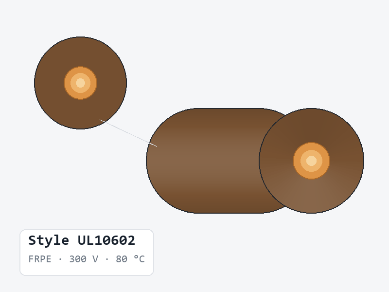
UL · E170689 is cited for this line. Request the issued document before relying on it for a finished-product approval.
Request certificate or datasheet →UL10602 is a FRPE-insulated hook-up wire manufactured by Xinya Electronic Co., Ltd. It is rated 300 V, 80 °C. It is supplied in 24 recorded constructions spanning 16–32 AWG, with an overall diameter of 0.7–11.45 mm, cut to the length you order.
UL10602 at a glance
- 16–32 AWG, across 24 listed constructions
- Both solid (single-strand) and stranded conductors are listed — 9 solid and 15 stranded
- Insulation wall 0.25–0.31 mm
- Overall diameter 0.7–11.45 mm
- Max. conductor resistance 14–595 Ω/km at 20 °C DC (roughly 4.3–181.4 Ω per 1,000 ft)
- Routine withstand test on every listed row: 2000 VAC, 1 min
How UL10602 compares with its nearest alternatives
UL10602 and UL10800 share the 300 V rating and 80 °C temperature rating. Overall diameter runs 0.7–11.45 mm for UL10602 against 2.1–3.8 mm for UL10800. UL10800 is the tighter of the two, so UL10602 is the option to take only when the larger diameter is acceptable. Insulation wall is 0.25–0.31 mm against 0.4–0.46 mm. Size coverage is 16–32 AWG against 16–30 AWG.
UL10602 and UL3346 share the 80 °C temperature rating. The distinction is in voltage rating (300 V against 150 V). Overall diameter runs 0.7–11.45 mm for UL10602 against 0.75–2.15 mm for UL3346. UL3346 is the tighter of the two, so UL10602 is the option to take only when the larger diameter is acceptable. Insulation wall is 0.25–0.31 mm against 0.27–0.34 mm.
Conductor construction and selection
Both conductor families are listed. Single-strand rows such as 1/0.20 at 32 AWG suit fixed routing and insulation-displacement termination, where the conductor is not flexed after installation. Stranded rows such as 7/0.08 at 32 AWG flex repeatedly and are the usual choice for hand-soldered harnesses and anything that has to follow a moving path. Conductor resistance is the same at a given size, so the choice between them is mechanical rather than electrical.
How to read the UL10602 table
“Insulation O.D. (mm)” is measured over the insulation, not over a jacket, tape or braid. Conductor resistance is stated at 20 °C DC per kilometre — divide by 3.281 for ohms per 1,000 ft. The withstand column is a routine production test applied to finished lengths, not a continuous working voltage.
Questions buyers ask about UL10602
Which sizes of UL10602 are available?
16–32 AWG, across the 24 constructions in the table below. Sizes outside the table can be quoted on request.
Can UL10602 be supplied in both solid and stranded conductor?
Yes. The documented range covers 24 constructions, of which 9 are single-strand and 15 are stranded. Give the construction, not only the AWG, when you request a quotation.
What overall diameter does UL10602 run to?
The documented range is 0.7–11.45 mm. Quote the size, not the style alone, when the diameter has to fit a specific gland, grommet or channel.
Detailed specification table
Manufacturer construction data for UL10602. Values are transcribed from the source specification sheet. Confirm the final construction and order requirements during quotation.
Scroll horizontally to view all specifications
| AWG | Construction | Conductor diameter (mm) | Insulation thickness (mm) | Insulation O.D. (mm) | Max. conductor resistance (Ω/km, 20°C, DC) | Dielectric strength (VAC, 1 min) |
|---|---|---|---|---|---|---|
| 32 | 1/0.20 | 0.20 | 0.25 | 0.70 | 563 | 2000 |
| 32 | 7/0.08 | 0.24 | 0.26 | 0.75 | 595 | 2000 |
| 30 | 1/0.254 | 0.25 | 0.25 | 0.75 | 361 | 2000 |
| 30 | 7/0.10 | 0.30 | 0.25 | 0.80 | 381 | 2000 |
| 28 | 1/0.32 | 0.32 | 0.27 | 0.85 | 227 | 2000 |
| 28 | 7/0.127 | 0.38 | 0.26 | 0.90 | 239 | 2000 |
| 28 | 7/0.127 OS-1* | 0.38 | 0.26 | 0.90 | 239 | 2000 |
| 26 | 1/0.404 | 0.40 | 0.25 | 0.90 | 143 | 2000 |
| 26 | 7/0.16 | 0.48 | 0.26 | 1.00 | 150 | 2000 |
| 26 | 7/0.16 OS-1* | 0.48 | 0.26 | 1.00 | 150 | 2000 |
| 24 | 1/0.511 | 0.51 | 0.25 | 1.00 | 89.3 | 2000 |
| 24 | 7/0.20 | 0.60 | 0.25 | 1.10 | 94.2 | 2000 |
| 24 | 7/0.20 OS-1* | 0.60 | 0.25 | 1.10 | 94.2 | 2000 |
| 22 | 1/0.643 | 0.64 | 0.25 | 11.45 | 56.4 | 2000 |
| 22 | 7/0.254 | 0.76 | 0.27 | 1.30 | 59.4 | 2000 |
| 22 | 7/0.254 OS-1* | 0.76 | 0.27 | 1.30 | 59.4 | 2000 |
| 20 | 1/0.813 | 0.81 | 0.27 | 1.35 | 35.2 | 2000 |
| 20 | 7/0.32 | 0.96 | 0.27 | 1.50 | 36.7 | 2000 |
| 20 | 7/0.320 | 0.96 | 0.27 | 1.50 | 36.7 | 2000 |
| 18 | 1/1.024 | 1.02 | 0.27 | 1.55 | 22.2 | 2000 |
| 18 | 16/0.254 | 1.17 | 0.31 | 1.80 | 23.2 | 2000 |
| 18 | 7/0.404 OS-1* | 1.20 | 0.30 | 1.80 | 23.2 | 2000 |
| 16 | 1/1.29 | 1.29 | 0.25 | 1.80 | 14.0 | 2000 |
| 16 | 26/0.254 | 1.49 | 0.31 | 2.10 | 14.6 | 2000 |
Source specification sheet: 10602.
Request a quote for this line
Tell us the style, AWG, colour and quantity — or attach nothing and just describe the requirement. We reply to every enquiry.